CALL 800-985-6929
Mon-Fri 7AM - 7PM CST
Motor Options and Construction
NORD motors are either assembled from component parts or stocked as complete motors ready to be assembled to a gear unit or shipped as a stand alone motor.

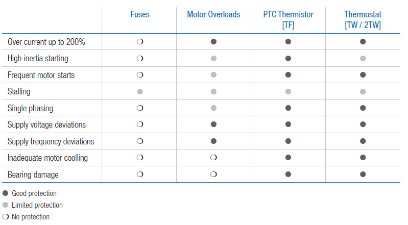
Motor Overload Protection
Selecting appropriate motor protection is a key factor in reliable motor operation. There are two common classes of motor protection — current based and temperature based.
Electrical installation codes require at least two types of protection in the motor circuit, both of which are normally current based. First is short-circuit protection that is accomplished by fuses or circuit breakers.
The second is motor overload protection and is typically a device called a “motor overload” or a “heater.” NORD can provide two different types of motor temperature based protection — a PTC thermistor (TF) or a bi-metallic
thermostat (TW). In many situations, temperature based protection is often the more effective motor protection.
Thermostats (TW & 2TW)
Motor thermostats, or bi-metallic switches, can be wired directly into the control circuit without a separate control module or tripping device. Thermostats operate on a relatively high control voltage so they are less sensitive to voltage interference from the main power supply. Thermostat leads and motor power leads can be ran next to each other when using the appropriate shielded cable. The installer is responsible for wiring the thermostats onto the motor control circuit. The leads may be labeled in a variety of ways as indicated.

Thermistors (TF)
With a separate control module or tripping device (ex. Kirwan INT69), thermistors are used to sense overload and temperature conditions by converting the critical operating temperature limit into internal resistance changes.
Many variable frequency drives are available to accept thermistors without requiring the seperate contol module.
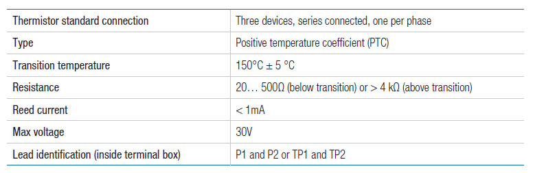
Due to their small size, heat sink construction, and high change in resistance value, minor resistance variations caused by relatively long lead runs may be tolerated. This feature also allows for one controller to be used for several temperature sensing locations. Many VFDs come with on-board thermistor inputs. NORD does not supply the thermistor control module.
Thermostats and thermistors will automatically reset. All wiring must be completed by qualified personal and adhere to all local installation codes.
Space Heater (SH)
Anti-condensation space heaters heat up motor windings to prevent moisture from forming inside the motor. Space heaters are recommended in case of severe temperature fluctuations, high humidity, or extreme climatic conditions. The required voltage must be stated when ordering. Available versions: 115V, 230V, 460V Space heaters must not be switched on while the motor is running.
Single Phase Motors, 60Hz (ECR)
ECR single phase motors are intended for demanding operation on a 60Hz power supply. The permissible voltage is 115V +/-10% or 230V+/-10%. ECR motors contain both a run-capacitor as well as an additional start-capacitor that is switched off after start-up. They are suitable for applications that demand higher starting torque and generally have a 1.35 SF if operated within the allowable voltage range.
Condensation Drain Holes
Condensation drain holes are placed in the motor endbells at the lowest possible point and allow for accumlated condensation to drain. The motor drain holes can be provided by NORD either open (KBO) or sealed with a closing
plug (KB).
The motor must be installed in the mounting orientation specified on the nameplate or the drain holes will not function properly and may result with the motor filling with water.
Condensation Drain Holes, Plugged (KB)
KB drain holes are plugged for shipment. The plugs must be removed before commissioning in order for the holes to effectively drain moisture.
Condensation Drain Holes, Open (KBO)
KBO drain holes are shipped open (not plugged).
IP66 Enclosure Protection
IP66 protection includes all features of IP65 enclosure protection and is suitable for wet, high-pressure wash down, and extremely dusty environments.
Terminal Box Sealed with Resin (KKV)
Terminal boxes may be sealed with a flexible, electrically safe resin to ensure that contaminants, water, and moisture cannot pass through the terminal box into the stator body. This option is helpful in extremely dusty, wet, and humid
environments as well as installations that frequently have large temperature swings where condensation may form.
For extreme wet environments, the terminal box can be fully filled with resin. In these instances, the motor must be supplied with a quick disconnect plug pre-wired for the proper voltage.
Additional Insulation (AICM)
NORD offers additional insulation inside the motor for greater electrical protection in extremely wet or corrosive environments. An electrically safe insulating material is applied internally to the stator windings and the rotor body.
Epoxy Dipped Windings (EP)
In extremely wet environments, the motor windings are dipped in epoxy for improved moisture protection. The motor can also be treated with a variety of protective coatings including NSD2 or above for an even higher degree of protection.
Canopy Drip Cover (RD)
NORD offers a canopy drip cover for wet or dirty installations where the fan end of the motor is mounted up. This blocks falling water or debris and forces it to repel from the motor’s fan guard.
Double Fan Cover (RDD)
For wet or dirty installations where the fan end of the motor is mounted up, the NORD double fan cover provides protection from falling / wind blown water, snow, dirt, or debris entering the back of the motor.
Totally Enclosed Non-Ventilated (OL)
TENV motors provide benefits in operating environments such as those with extreme dust or dirt and where cooling fans may accumulate material that can be detrimental to the motor and application. The motors can also be used to reduce cooling fan noise on a standard motor. TENV motors feature the standard fan cooled motor design, including the fan cover, but are provided without the fan.
A TENV motor requires either a larger motor frame size or a reduced power rating applied to the standard frame. A standard motor frame size can operate as a TENV motor at full rated power provided that the duty cycle is intermittant at 50% ED or less.
Totally Enclosed Non-Ventilated, Without Fan Cover (OL/H)
The OL/H series of TENV motors are more compact in space than the OL series. They do not include the rotor shaft extension through the back bearing end bell or the fan cover.
2nd Shaft Extension on Fan Side (WE)
NORD offers a second shaft extension on the fan side of the motor that protrudes through the fan cover. This extension can be used as a power take-off or to mount customer supplied devices such as encoders and tachometers. The shaft extension can be provided on motors with and without brakes. The shaft extension can not be used on motors with blower fans (F) or (FC).
Hand Wheel (HR)
Motors can be supplied with a hand wheel that is located on the second shaft extension. The hand wheel can be used for manual operation during power outages or for machine positioning setup. This option is offered on metric WE shafts only.
Small Terminal Box (EKK)
The motor terminal box can be provided as a smaller, one-piece terminal
box design. This option is valid for standard motors 0.16 – 10.0 hp (frame size 63 – 132). When supplied with a brakemotor, the brake rectifier must be
located outside of the terminal box.
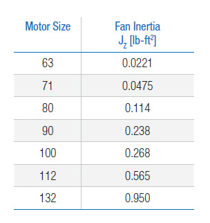
High Inertia Cast Iron Fan (Z)
An optional cast iron motor cooling fan is available for use as a mechanical
soft start and/or soft stop and to add inertia to the motor. These fans can also be used for a flywheel effect to store mechanical energy and smooth rapid load changes. Cast iron fans replace the standard nylon motor fan. The motor length is the same as a brakemotor.
Motor Backstop (RLS)
Back stops are used to prevent backward rotation from the load when the motor is switched off. A drive with a back stop can only run in one direction and the required direction must be stated when ordering.
Caution for motors with more than 4 poles and FI operation. It is essential to observe the lift-off speed. The back stop only operates without wear above the lift-off speed.

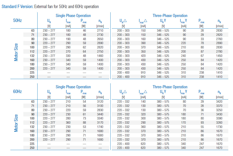
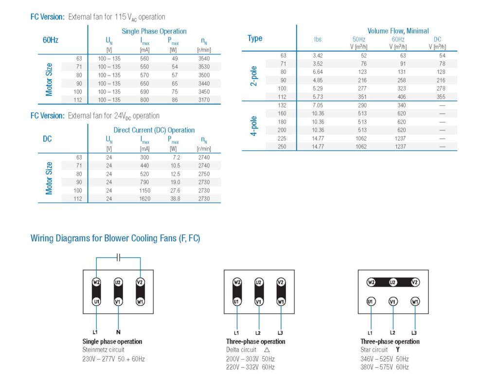
Blower Cooling Fan (F, FC)
Typical applications for external fans are drives which are controlled by VFDs
that are operated over a long period at low motor speeds and full nominal
torque. External fans are also frequently used for applications in cyclic
operation with high switching frequency (S4 mode).
The version is standard with
ISO class F (24 VDC special version ISO class E)
Protection class IP66
CE + cURus approval
External fans on NORD motors are universally suited for 50Hz and 60Hz
operation in single phase and three-phase networks. All external fans have
a separate terminal box and are available in special design with a HARTING
plug connector.
External fans cool the motor regardless of the speed and with appropriate
switching, can also function even when the motor is switched off.
The external fan must be connected separately from the main motor and the
main motor should be protected against failure of the external fan by using
thermistors (TF).
The external fans are as follows according to the motor sizes:
Size 63 – 112 2-pole
Size 132 – 250 4-pole
Standard Circuit for External Fans:
Single phase operation / Steinmetz circuit
for motor sizes 63 – 90 (230V standard) and motor size 63 – 112
(115V FC version)
Three-phase operation r- or Y- Circuit
for motor sizes 100 – 250

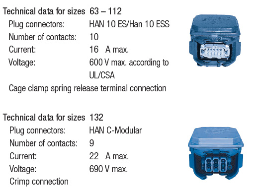
Quick Power Plug Connector (MS)
MS connectors are available on NORD three-phase motors and brake
motors from frame size 63 – 132. After the first installation, the motor
can be quickly changed by simply plugging and unplugging the electrical
connections.
With frame sizes 63 – 112, a HAN 10 ES male connector is used on
the motor side. On the customer side, a HAN 10 ES female connector is
required (Harting). Above size 132, a male HAN C Modular is provided
on the motor side. NORD also supplies a protective plastic cover on the
connector to protect from dirt and damage prior to installation.
The power plug position must be specified when ordering. The standard
configuration is shown in position II with the connector mounted on the
side of the terminal box pointing toward the fan cowl. Plug connectors are
also possible for positon I or III.
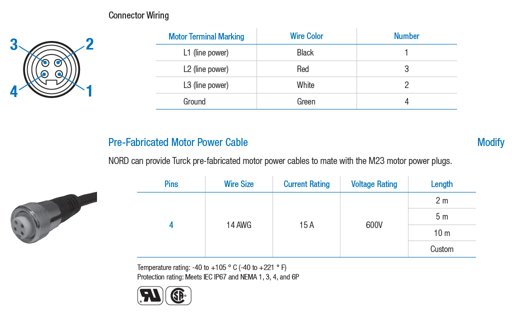
Round Motor Power Connector (RS)
NORD can provide a variety of motor power plug connectors that allow for a safe and quick connection/disconnection of the motor’s main power supply. The following M23 plug options are stocked for NORD motors up to 5.0 hp and can be used with standard NORD AC motors and brake motors powered from the motor’s terminal block. The M23 plug provides three pins for line power and one pin for ground at the motor connection.

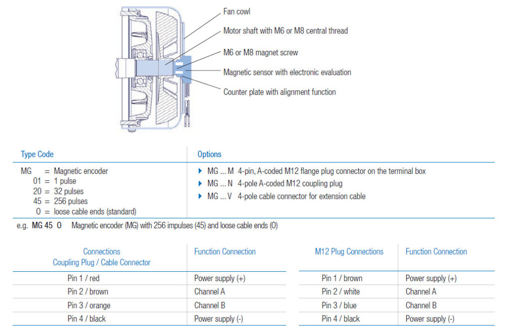
Magnetic Incremental Encoder (MG)
A flexible, reliable incremental encoder system is available for NORD motors with axis heights from 63 to 180. The system operates on the basis of a contactless magnetic measuring principle and does not require separate bearings.
Because of this, it is extremely resistant to vibrations and is not sensitive to impacts which act on the drive unit.
Encoders are mounted on the B side of the motor using a threaded hole on the shaft while the evaluation sensor is mounted on the fan cowl. The alignment of the system tolerates +/- 1 mm in all three axes. Due to the special design of the magnetic system, use in the vicinity of electrical brakes is also possible.
The encoder provides two output channels (track A and B) which deliver pulse flanks staggered by 90°, effectively enabling detection of the rotational direction and quadrupling the number of pulses. The lowest resolution supplied by NORD is
provided by an encoder with 1 pulse per revolution (1 ppr), delivering a “1” and then a “0” for each 180° of rotation of the motor shaft. This monitoring does not require a fast PLC or counter input.
Pulse time may fluctuate slightly as the absolute accuracy is typically 200 ppr.

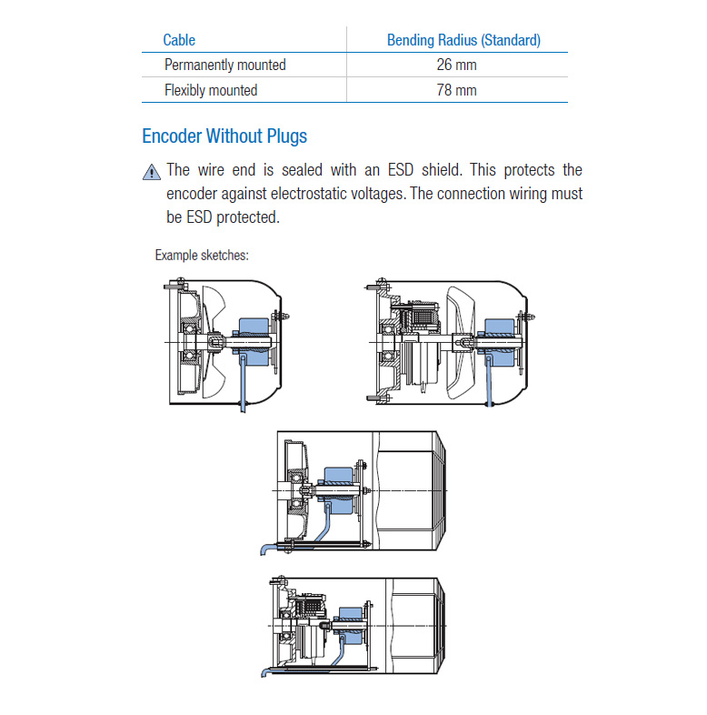
Magnetic Encoder System Mounting
Mounting of the magnetic encoder system is very simple due to an automatic alignment function automatically tightening the screws on the fan cowl
and the sensor housing.
In the subsequent trial run, the auxiliary alignment cams are slightly worn down by the counter plate. The connection cable is then fastened to the fan
cowl and passed to the terminal box according to the version.
Incremental Encoder (IG)
Incremental encoders convert rotary movement into electrical signals and are often used in modern applications to report speed feedback. Signals are read out and processed by frequency drives or other control devices. Incremental encoders operate according to the photoelectric method by scanning a disc with alternating lines and spaces.
The integrated electronics convert the measuring signals into a digitalized square wave signal according to TTL or HTL logic — there are types with differing resolution/pulse numbers. Standard encoders have 4096 pulses per rotation.
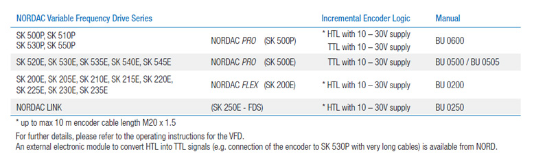
The following configurations can be implemented in combination with NORD frequency encoders:

Incremental Encoder Mounting
Encoders can be mounted on motor sizes 63 to 225.
The motors can be either self-ventilated or externally ventilated, with or without brakes. NORD hollow shaft push-in encoders are mounted directly on the B side shaft end of the motor, protected by the fan cowl.
This ensures a secure, torsion-free coupling of the encoder.
Electrical connection is via a pre-assembled cable (as standard, 1.5 m long with open wire ends; other lengths or versions with plugs are also possible).
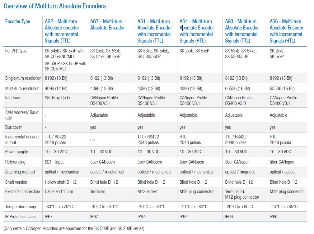
Absolute Encoders (AG)
Absolute encoders are encoders for rotational movements and output absolute position information in the range of a revolution of the motor (360°, single-turn) or additionally, the number of rotations with reference to a zero point (multi-turn).
Typical values are 8192 (13 Bit) steps per rotation and with multi-turn, 4096 (12 Bit) distinguishable rotations.
Single-turn encoders are mounted on the output side of the system (typically turntables) whereas multi-turn encoders are mounted on the output side of the gear unit or directly on the motor.
With absolute encoders the rotations are measured either entirely electromagnetically or mechanically by means of small gear stages that reduce the speed of additional bar code discs.
Advantages Over Incremental Encoders for Positioning Applications
Position information is always up to date, even changes of position when no voltage is present or in the case of lost or impaired pulses.
Absolute encoders cannot be used for speed control (with NORDAC VFDs) however, combined encoders with absolute and additional incremental encoder signals are available. Absolute encoders with various data protocols such as DDI, CANopen, and Profibus are also available — selection depends on the evaluation electronics.