CALL 800-985-6929
Mon-Fri 7AM - 7PM CST

Brake Selection
The selection of a motor brake system is broken down into five phases:
1. Selection of the braking torque
2. Selection of the braking times (release times and setting times)
3. Selection of the electrical supply and connection
4. Selection of brake options
5. Verification of the permissible brake work
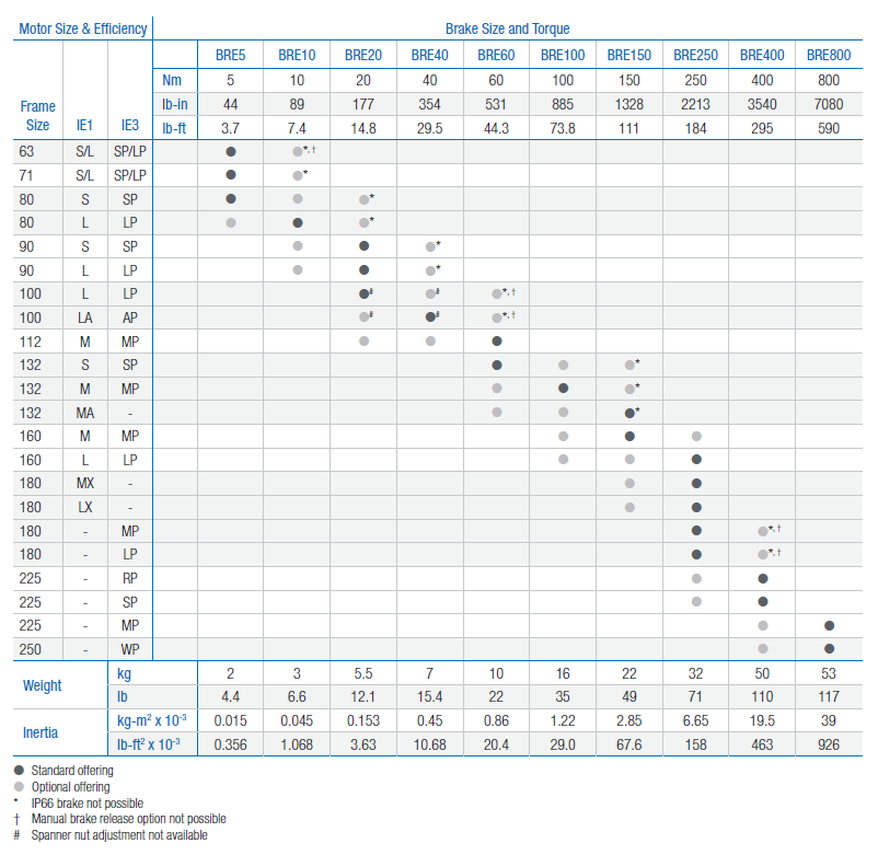
Each NORD motor may be supplied with a number of brake torque sizes
and adjusted to different brake torque values. The BRE value in the table
on page 53 is the standard brake torque size for each motor.
Example for ordering: SK 32 S/4 BRE10 (BRE 10 indicates a brake
torque size of 10 Nm)
The design of the drive units is orientated to both the torque required for
the application and the motor torque. If necessary, the braking torque
must be considerably reduced so that there is no overload of the gear
unit when large moving masses are braked.
General Selection Considerations
The brake size must be specified according to the requirements of the
application while considering the following:
For most applications, we advise sizing the brake to 1.5 – 2 times the
motor rated torque
For vertical applications, it may be advisable to size the brake size up
to 3 times the motor rated torque
For some applications, it may be necessary to specify a reduced brake
torque setting to prevent excessive peak load conditions developed at
the reducer output
On travel drive applications, excessive brake torque may lead to wheel
skid; for crane applications, excess hoist-cable swing can occur
Brake Motors
NORD brake motors are equipped with DC-excited spring pressure
brakes. The brakes prevent accidental rotation of machines (as holding
brakes) or bring rotation of the machine to a standstill (as a working
brake or for emergency stop).
Environment
The brake linings are environmentally safe and asbestos-free.
Safety
The braking action is activated upon interruption of the current (idling
current principle). The brake can no longer be released if the brake
linings are worn.
Idling Current Principle
The brake disc is located between the brake bearing cover and the
rotor plate and features a brake lining on both sides. Braking torque
is transferred to the motor shaft by means of the coupling. The brake
disc can be moved in an axial direction on the coupling. The rotor plate
presses the brake disc against the brake cover plate by means of spring
pressure and friction between the rotor plate / brake lining and between
the brake bearing cover / brake lining produces the braking torque. The
brake is then released by an electromagnet (magnetic component).
After the current is switched on, the electromagnet pulls the rotor plate
back from the brake lining by several tenths of a millimeter against
the pressure of the spring. This allows the brake disc to rotate freely.
Interruption of the current causes the magnetic force to collapse, so
that the spring pressure predominates. This allows the brake to be
automatically activated.

Power-to-Apply Principle
Brakes that are activated by the force of an electro-magnet are designated
as power-to-apply brakes. Contact NORD for more information.
Note:
The brake torque is measured with a mean friction radius of the brake pad surface with a circumferential speed of 1m/sec (197 fpm).
For different applications and operating conditions, brake torque can vary from +40/-20% compared to the rated brake torque.
Hoisting (lifting/lowering) applications must have the brake wired for fast response (DC-switching).
In new condition, the brake will have a reduced torque of up to 30%. In order to achieve full rated brake torque, a short run-in period is required. The run in time will vary depending on system loads.
The brake rotor or brake pad must be protected against foreign matter, oil and grease. Contaminants of this type can greatly influence wear and reduce breaking torque.
Brake Torque Adjustment (ADJ)
Brake torque adjustments are possible by changing the brake spring combinations or by removing springs.
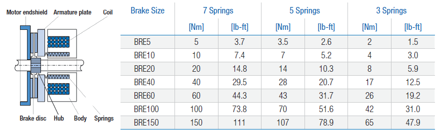
When adjusting the brake torque, start by removing the outer springs at opposite corners to prevent uneven brake wear.
On brake sizes 5 – 150 Nm (3.7 – 111 lb-ft) full brake torque is achieved with all (7) springs. The brake springs are placed in such a manner where there are (3) inner and (4) outer springs.
In addition, brake sizes from 5 – 40 Nm (3.7 – 30 lb-ft) are typically supplied with a threaded adjustment nut or spanner nut. Additional fine torque adjustment can be made by unscrewing the spanner nut a number of turns or “clicks” with
a spanner wrench.

Working brake and Holding brake
A working brake implements friction work in regular operation when the
motor power is turned off, i.e. performs a braking function. This brake
stops a moving load or application frequently and regularly, not only as
an occasional or special case. Any non-inverter application needing
braking requires a working brake.
A holding brake does not implement any friction work in regular operation,
but only serves to secure an already stopped load or application. This
brake is typically used with a frequency inverter and is engaged once the
frequency inverter has already brought the application to a stop. A holding
brake may perform a braking function in the event of an emergency stop
or power loss but must be sized according to the maximum permissible
work per cycle for that brake.
Examples for Holding brake and Working brake
Working brake
The geared motor is directly supplied by the line voltage supply. To
slow down the application when the motor is powered off at speed, the
mechanical spring-loaded brake must generate a braking torque and
thus performs friction work.
Holding brake
A frequency inverter controls the acceleration and deceleration of the
application. The mechanical spring-loaded brake is only applied after
the application has come to a standstill. The brake is therefore only used
for “holding” the application (parked position). It does not perform any
friction work. Only in the event of an emergency stop or power failure is
friction work done while moving.
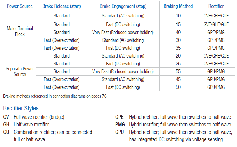
Brake Times and Electrical Selection
Brake timing performance is critical in selecting the optimal brake system.
NORD brakes provide exceptional performance in terms of the release
(start) times and engagement (stop) times. Use the following guidelines
in order to select the correct brake control components and connections.
1) Determine if the brake needs to be wired directly from the motor
terminal block or powered by a separate source.
If you are using an AC vector drive, soft-start, or a two-speed motor you will need to supply the rectifier from a seperate power source.
If the motor is powered direct across-the-line, the rectifier power can be supplied from the motor’s terminal block
2) What type of performance is required?
Is the standard brake performance OK?
Is a higher performance required for fast brake release or very fast
brake stopping?
3) Determine the brake supply voltage and check rectifier compatibility
When Fast or Very Fast Stopping is Recommended
Any applications that require quick stops and positive action at stand-still,
as well as all vertically mounted applications.
Recommended Applications
Conveyors and inclined conveyors
Hoists and lifts
Bulk material handling equipment (bucket elevators, idler conveyors)
When Fast-Release is Recommended (Overexcitation)
Any application that is very high-cycling with frequent starts and stops.
These applications require the brake to release very quickly in order to
avoid excessive heat build-up in the AC motor and brake coil.
Recommended Applications
Index conveyors
Diverters
Storage and retrieval crane systems

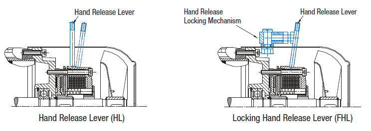
Hand Release Lever (HL)
The hand release option allows the brake to be manually released without requiring that the brake be energized with voltage. The lever has a spring return that allows the brake to be hand released and returned automatically to its set position. The hand release lever can be unscrewed for easy removal.
Locking Hand Release Lever (FHL)
This option allows the brake to be manually released and locked off without requiring voltage to the brake. The lock mechanism prevents the spring from returning the brake to a closed state without manual action by the user. The hand
release lever can be unscrewed for easy removal.
Hand Release Lever With Hole (HLH)
Hand release levers can be provided with a 5.5 mm through hole. The hole can be used for attaching external pulling devices such as a cord to release the brake at a distance. This option is available for brake sizes BRE5 to BRE60.
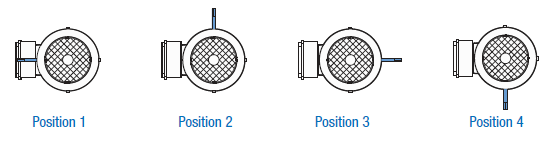
Hand release lever location is required for HL, FHL, and HLH options.
Corrosion Protected Brake (RG)
The brake is fitted with a stainless steel brake plate to provide additional protection in severe and wet environments.
Dust and Corrosion Protected Brake (SR)
A rubber-sealing boot is installed on the brake to provide additional protection in dusty environments. This feature includes the stainless steel brake plate (RG).
IP66 Brake Enclosure (IP66)
A sealed brake with IP66 enclosure protection can also be provided. This brake has a different mechanical housing that provides a higher degree of protection against severe environments.
Brake Heating
Brakes can be provided with a number of different heating systems. Contact NORD to discuss the details of your application.

Quiet Brake Release (NRB1)
To reduce the noise of the brake release, an o-ring can be placed between the brake coil body and the armature plate (stationary disc). The o-ring dampens the impact caused by the armature plate hitting the brake coil body during the release process. When ordering NRB1, the SR (dust boot) option is required. The SR option also includes the RG stainless steel corrosion plate.
Quiet Brake Operation (NRB2)
Noise due to vibration in the brake components is possible during motor operation particularly with variable frequency drives or single phase motor operation. To reduce this vibration, the brake can be constructed with an o-ring between the brake carrier hub and the brake disc. This o-ring will prevent the clattering caused by the rapid micro speed changes in the motor caused by the VFD or single phase operation.
Double Brakes for Theatrical Applications (DBR)
Many international standards for braking systems used on theater hoists mandate the use of brakes that automatically set when power is removed. Redundancy is also required with the system brakes. If one brake fails, the other brake can still operate the system by running independently and parallel to each other. NORD DBR (2xBRE) brake systems are designed to meet these requirements. NORD double brakes are also designed for quiet operation < 50dB(A).
Contact NORD for engineered selection.
Micro Switch (MIK)
The micro switch monitors the release state of the brake and can be wired into external control circuitry to provide additional safety. The switch can also be used to detect certain brake service problems including excessive brake wear.


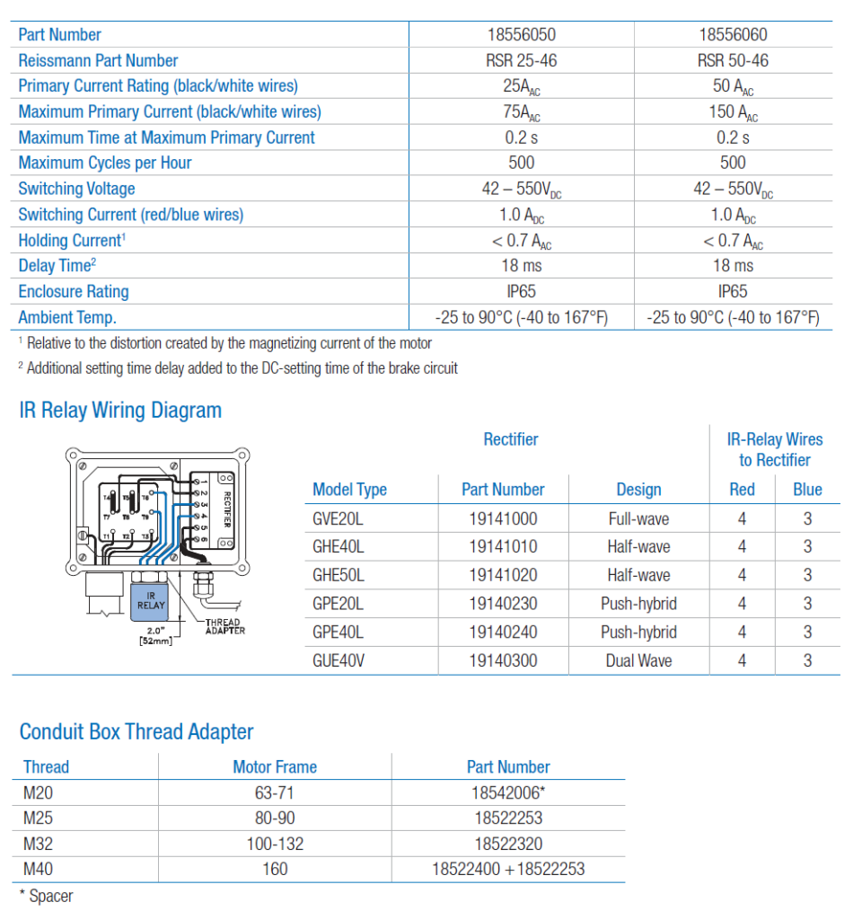
Current Sensing Relay (IR)
The current sensing relay is used to achieve a fast brake engagement (stopping) without the use of external control equipment or additional wiring. The relay is mounted directly on the conduit box, and is powered from the motor’s terminal block. The power leads for the relay replace one of the brass jumper bars on the terminal block of any single speed motor and the switch leads are connected to terminals 3 and 4 of the rectifier. When the power to the motor is shut off, the IR relay opens the brake circuit on the DC side which allows the brake to de-magnetize quickly.
Brake must be powered from the motor’s terminal block (not seperately powered). Motor must be single speed and should not be powered by a VFD or soft starter.